Saturday, November 14, 2009

Omegle.com Man In The Middle Attack

The other day my friend showed me this site Omegle. It's a pretty cool site that anonymously pairs you up with a 'stranger' and you chat 1 on 1 with the ability to disconnect and find a new 'stranger' at any time. It's surprisingly addicting and fun. It claims to be completely anonymous and so to check this I decided to fire up Wireshark and take a look at what information was getting passed to the server. I was surprised to find the method of communication extremely simple and completely unencrypted. When you connect to a person the process looks like this:

You: POST omegle.com/start
Omg: HTTP "123456" <-- random 6 digit 'username' (a-z A-Z 0-9 _ -)
You: POST omegle.com/events?id=123456
Omg: HTTP [["connected"]]
You: POST omegle.com/send?msg=hello&id=123456
Omg: HTTP win <-- funny
You: POST omegle.com/events?id=123456
Omg: HTTP [["gotMessage", "hey"]] <-- message from other person
...
You: POST omegle.com/disconnect?id=123456 <-- quit the chat


Seeing this immediately sparked some thought. Can I request events for other users? Can I send messages to other users? Can I disconnect other users? It seemed all you needed to do was post the command with the user id you wanted to receive events for. As it turns out its almost even better. If you post for events using someone elses user id it will "implode" their chat:

Screenshot


Whats better is that the other person is still connected and they have no idea that their 'stranger' has been imploded. Now you can keep talking to the other person and they have no idea what just happened.

There is one major problem with this however. According to:

http://omegle.com/count

there are on average only about 3k users online at a given time, but the number of possible user ids are

(26+26+10+1+1)^6 = 68,719,476,736

That is a terrible chance of you finding someone quickly. I actually started making a brute forcer (omegle_brute_force.py) but quickly realized that this was an ill fated attempted.

So if you cant find the users, why not have the users come to you? I realized that Omegle would be prime for a classic man in the middle attack. The idea is super simple. I would connect to two strangers just like normal, but instead of me talking to them they would talk to each other through me. As long as I don't inject any messages or anything weird they should have no idea that I'm even there. Here is how the program looks:

omegle


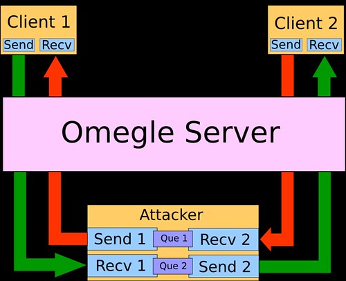
As you can see I am having a legit connection to both client 1 and client 2, but I am transparently passing their messages right through me to the other person.

Doing this was kinda tricky. Whenever you POST for events it blocks until the read is fulfilled. This means that with a single threaded program each person would have to take turns talking since the program would block every time I polled for their messages. Even most two threaded setups have the same problem. The solution I came up with I feel works pretty well. There are four total threads:

1) Sending to client 1
2) Receiving from client 1
3) Sending to client 2
4) Receiving from client 2

Every time the receive thread gets a message it queues it into a stack, so that the sending thread can retrieve the message at its leisure. The result? It doesn't matter if a POST blocks because the sender thread can still work through the queue and the other threads can still send and receive messages.

A classic man in the middle attack:

Screenshot-2

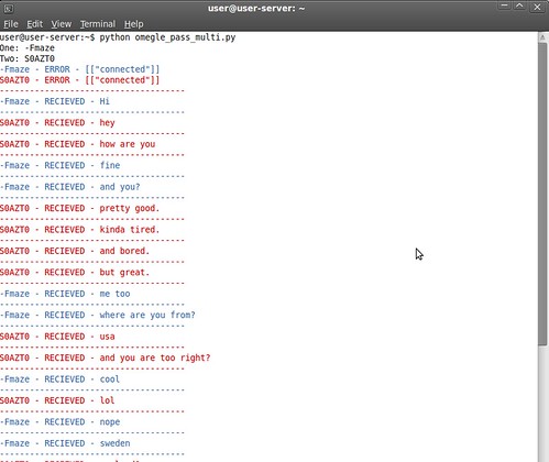
This has some interesting possibilities. I can send messages to one of the clients at the others behalf and the person will have no idea that I sent it. Also what about connecting more then 2 people together? There is no reason I couldn't connect multiple people together in a chat and maybe even append a user tag to each of their messages.

Omegle is a pretty interesting site, and you gotta hand it to Leif K-Brooks for (apparently) single handedly making such a propular site at only 18. I hope that he can implement some needed security to Omegle to prevent this kind of attack in the future.

Download my programs here [mirror].

omegle_man_in_middle.py - program described above
omegle_brute_force.py - attempts to guess user ids and post for events
omegle_class.py - generic class for interacting with omegle
omegle_connect_view.py - connect to omegle and posts for events
omegle_multi_connect.py - connects to multiple people at once. proof of concept that multi connections can be made
omegle_send.py - send messages using a user id

EDIT:

Found another omegle man in the middle attack written in perl [here]

Sunday, November 8, 2009

PS3 Eye Driver Patch

Update: A lot has happened since this was posted. The main line kernel now includes most of these fixes!

I've had a PS3 Eye lying around for a while but I hadn't gotten around to using it because when it first came out there were no drivers for it so it sat in my closet for almost a year. I decided to check out the current state of the PS3 Eye in Linux and was happy to find that there is now support in the 2.6.31 kernel.

What I was disappointed to find out though was that there was no ability to select frame rate or control a lot of the image quality. Lucky there is patch that allows selection of frames rates all the way up to 125 fps and some image quality controls. I patched my driver and tried it out but found that the color of the image was way off and none of the given controls could fix this.

I decided to do some research and add support for brightness, contrast, hue, and auto white balance.

before
With Kaswy's Patch


driver
With my patch


I'm going to just supply the whole .c file instead of a patch since they are almost the same size. Applying the patch is almost the same as Kaswy's

To apply:

Install necessary packages:

$ sudo apt-get install kernel-package libncurses5-dev wget bzip2 build-essential linux-source


Extract kernel source code:

$ sudo su
$ cd /usr/src
$ tar --bzip2 -xvf linux-source-2.6.(your version).tar.bz2
$ ln -s linux-source-2.6.(your version) linux


Replace driver:

$ cd linux
$ wget ucfilespace.uc.edu/~thrunml/ov534.c
$ rm drivers/media/video/gspca/ov534.c
$ mv ov534.c drivers/media/video/gspca/


Recompile driver:

$ cp /usr/src/linux-headers-$(uname -r)/Module.symvers /usr/src/linux
$ make oldconfig
$ make modules_prepare
$ make SUBDIRS=drivers/media/video/gspca modules


Install new driver:

$ cp drivers/media/video/gspca/gspca_ov534.ko /lib/modules/$(uname -r)/kernel/drivers/media/video/gspca
$ depmod


Check to make sure it installed:

$ modinfo gspca-ov534
filename: /lib/modules/2.6.31-14-generic/kernel/drivers/media/video/gspca/gspca_ov534.ko
license: GPL
description: GSPCA/OV534 USB Camera Driver(kaswy mod for MT use V0.5 / bear24rw patch V0.1)
author: Antonio Ospite
srcversion: 1F87820D2B0705822B61A16
alias: usb:v1415p2000d*dc*dsc*dp*ic*isc*ip*
depends: gspca_main
vermagic: 2.6.31.4 SMP mod_unload modversions
parm: videomode: = xx //Set the videomode(see doc) (int)
parm: autogain: = [0|1] //Autogain (agc,aec,awb) (bool)
parm: gain: = [0..63] //main gain (int)
parm: awb: = [0|1] //Auto White Balance (bool)
parm: exposure: = [0..255] //Exposure (int)
parm: brightness: = [0..255] //Brightness (int)
parm: contrast: = [0..255] //Contrast (int)
parm: redblc: = [0..255] //Red Balance (int)
parm: blueblc: = [0..255] //Blue Balance (int)
parm: hue: = [0..255] //Hue (int)
parm: sharpness: = [0..63] //Sharpness (int)
parm: vflip: = [0|1] //Vertical flip (bool)
parm: hflip: = [0|1] //Horizontal mirror (bool)


Now we can remove the one currently in use and load our new one:

$ modprobe -r gspca-ov534
$ modprobe gspca-ov534 videomode=10


The available video modes are:

00: 640x480@15
01: 640x480@30
02: 640x480@40
03: 640x480@50
04: 640x480@60
10: 320x240@30
11: 320x240@40
12: 320x240@50
13: 320x240@60
14: 320x240@75
15: 320x240@100
16: 320x240@125


You can adjust the image using guvcview

$ sudo apt-get install guvcview
$ guvcview


Hopefully the main line driver gets patched soon with these enhancements.

Thursday, October 1, 2009

LED Matrix

Last year in one of my classes we were required to make an 'artefact' or something that reflects the interests of the class. Most people make posters and the past two quarters that's what my class did too. Posters however are static, usually boring, and don't reflect that fact that everyone in the class is an EE major. We decided posters are for noobs and decided to go off the wall a little and make an LED matrix display. Lucky one of my friends John Wathen already had this beautiful 16x24 Green SMD LED matrix that he built back in high school.

P5271009

P5271014

What we didn't have however was a driver for it. The driver we choose to design was highly inspired from this one. The basic idea is that you use shift registers to sink the columns and a line driver of some sort to source the rows (we chose to use a Darlington array).

There where a lot of changes from the Instructables design that that we had to make however. The matrix in the Instructables was a lot smaller than ours and used 8 IO lines to drive each row. Since our matrix has 16 rows this was completely infeasible using just an ATMega168. To solve this issue we choose to use a 4:16 de-mux to control all sixteen rows with only 4 IO pins. The de-mux combined with two 8 channel Darlington arrays provided the perfect interface to control all 16 rows. To sink the columns we choose to string three 8 Output shift registers. Each shift register is rated to handle the current of the 8 LEDs that could possibly be on at one time.

Some other features that we included on the driver board were 3 green LEDs, 3 push buttons, ISP header, TTL header. When all was said and done we ended up the the schematic shown below.

rev_4


I know, you are probably looking at that and thinking, "Why are all the shift register outputs criss-crossed??". The reason for doing this is because the output pins on the chip are not exactly in a row so to assist in board layout the pins had to be crossed and mixed up so that the board layout would be nice. It's much easier to change the order of the columns in the program then it is on the board layout (in my opinion). We didn't want to etch a double sided board so a lot of effort went into laying as much of the circuit out on a single side. There were a few paths that could not be routed and were just jumped with wire (you'll see in picture below).

board


Notice how there are a bunch of air-wires (yellow lines) that I couldn't figure out how to route, they are manually jumped when the board is put together.

To etch the board we printed out the board layout 1:1 scale on glossy photo paper, it was than ironed onto a piece of copper clad. The idea is that the toner will stick to the copper clad and when the board is dipped in acid the acid will eat away at everything but the traces, since they are coved by the toner. I'm definitely not an expert in this area so ask John Wathen more about the process, he is basically a pro.

DSC_9192
Etching the board in acid

DSC_9193
Checking to see if its ready to be scrubbed

DSC_9199
Dirty traces

DSC_9205
Scrubbing off the rest of the toner

DSC_9217
The beautiful result, nice and shiny

Now, let me just tell you that we did this in a public bathroom at school. So there were three guys in a bathroom with latex gloves, a camera, and tub of some green liquid. Trust me we got some weird looks.

The next step was to drill all the holes. I don't remember exactly how many there were (John might) but there were a lot.

IMAG0015


After all the holes were drilled John soldered it all up.

P5271010

P5271011


And the result!

P5271017

P5271015

P5271013

P5271008

P5271007

P5271004

P5271005

P5271006

P5271019

P5271014


Now that the board was finished it was the moment of truth.

Adam Steele lent me his programmer. Plugged it into my Xbuntu box, apt-get installed the avr tool-kit and the programmer was immediately recognized (NICE!). Flashed a simple program to flash the status LEDs and low and behold, IT WORKED! Next up, everything else. I started by modifying the program that the Intructables provided but quickly got frustrated by the way it worked. It treated each column as a bit in a byte and the rows as a byte, this made it extremely hard to visualize outputs to the display. Also I was using a de-mux and had 24 columns which the code did not easy support. So what do you do in this situation? REWRITE.

An outline of how the new code works:

The value for each pixel is stored in a 2D array 16x24, want to set the top left pixel? buffer[0][0] = 1; simple as that, much easier than dealing with it as an array of bytes. Okay, so it takes up more memory but IMO it is completely worth every bit (pun intended).

The code starts by initializing the ports (pull-ups, in/out, etc) then it initializes timer1. To be completely honest the fill value for the timer was chosen by adjusting value, flashing, seeing if the refresh rate was noticeable. We ended up with OCR1A = 0x012C; as a good value.

The code then falls into an While(1) where it sequentially calls functions to draw stuff on the screen, for example:


All the high level functions (tunnel, spiral, shift, etc..) write to 'buffer'. When the timer interrupt goes off it calls the function shift_int() which reorders the columns into 'buffer_2' and then shifts them out to the shift registers. It then calls shift_mux() which jumps to the next row. So essentially we have a double buffered display.

Once all the low level code was done it was all fun and games. It was really nice being at the point were all you had to work with is a 2D array. We ended up with the high level functions:


It is so incredibly easy to make new functions when you are just manipulating a 2D array.

A warning before you watch the videos, they were taken with a crappy point n shoot camera so they look incredibly choppy. In real life the display is incredibly fluid and smooth. The videos do it zero justice.


Eagle Files & Source Code [Mirror]
If you re-use the design or source (which I encourage you to do) please give credit where credit is due. Also note that the entire code was literally written in a one night programming marathon since we were extremely pressed (read: it was due the next day), so there are still many bugs. Also I take no responsibility for any damage if you use my design and code (had to put a disclaimer ;))

Any questions regarding the design or the source code should be directed at me bear24rw . gmail.com
Any questions regarding the construction of the board should be directed at John Wathen jmwathen . gmail.com